Selected Courses on Digital Art-UOWM

15 Νοεμβρίου 2014

ARDUINO 05 MOOD CUE

Filed under: ARDUINO,NOTES ON INTERACTIVE ART — admin @ 14:15
1. Ορισμός του πυκνωτή – μονάδες χωρητικότητας
Πυκνωτής ονομάζεται η διάταξη εκείνη που αποτελείται από δύο αγώγιμες πλάκες οι οποίες χωρίζονται μεταξύ τους από κάποιο μονωτικό υλικό. Οι αγώγιμες πλάκες ονομάζονται οπλισμοί και το μονωτικό υλικό ονομάζεται διηλεκτρικό. Ο πυκνωτής έχει την ιδιότητα να συγκρατεί στους οπλισμούς του ηλεκτρικό φορτίο, όταν εφαρμοστεί μια τάση στα άκρα του. Η ποσότητα του φορτίου που μπορεί να συγκρατήσει ο πυκνωτής εξαρτάται από την επιφάνεια των οπλισμών του και την απόσταση μεταξύ των οπλισμών. όσο μεγαλύτερη είναι η επιφάνεια των οπλισμών και όσο μικρότερη η απόσταση των οπλισμών μεταξύ τους, τόσο μεγαλύτερο φορτίο μπορεί να συγκρατήσει. Το είδος του διηλεκτρικού υλικού παίζει πολύ μεγάλο ρόλο στην συγκράτηση του φορτίου που εκφράζεται με τον όρο χωρητικότητα.  ’ρα λοιπόν η ικανότητα ενός πυκνωτή να αποθηκεύει ενέργεια ονομάζεται χωρητικότητα.
Η χωρητικότητα ενός πυκνωτή συμβολίζεται με το γράμμα C και μονάδα μέτρησής της είναι το Farad. Επειδή το Farad (F), είναι μεγάλη χωρητικότητα στους πυκνωτές χρησιμοποιούνται υποδιαιρέσεις του Farad όπως βλέπουμε παρακάτω:
1F=1000mF, 1mF=1000μF, 1μF=1000nF, 1nF=1000pF. Για να είναι ποιο εύκολα κατανοητές οι μονάδες φανταστείτε μια σκάλα, με κορυφή την μέγιστη μονάδα χωρητικότητας και τελευταία την μικρότερη, όπως βλέπουμε κατά σειρά παρακάτω: F>mF>μF>nF>pF
Κάθε σκάλα που κατεβαίνουμε προς τα κάτω πολλαπλασιάζουμε Χ1000, ενώ όταν ανεβαίνουμε από κάτω προς τα πάνω διαιρούμε :1000. Έτσι για παράδειγμα ένας πυκνωτής που είναι 470nF είναι ίσος με 0,47μF, ή ένας πυκνωτής που είναι 2,2nF είναι ίσος με 2200pF.
#include

Servo myServo; //Create a new servo

int const potPin = A0; //Analog pin for the potentiometer
int potVal; //Values given by the potentiometer
int angle; //values that will modify the angle of the servo

void setup() {
  
  myServo.attach(9); //Makes a servo be controlled by pin 9
  
  Serial.begin(9600); //Initialize Serial monitor
  
}

void loop() {
  
  potVal = analogRead(potPin); //Giving potVal the values from the potentiometer
  Serial.print(“potVal: “); //printing in Serial monitor the values given by the potentiometer

  Serial.print(potVal);
  
  angle = map(potVal, 0, 1023, 0, 179); //mapping helps to convert the values from the potentiometer (0-1023) to values accepted to the servo (0-180)
  Serial.print(“, angle: “); //Printing out the angle value.
  Serial.print(angle);
  
  myServo.write(angle); //Actually making the servo moving, as the angle value changes.
  delay(15); //does all those instructions in 15 milliseconds.
  
}

[youtube https://www.youtube.com/watch?v=FxvzefTUJNk]

ARDUINO 04 COLOR MIXING LAMP

Filed under: ARDUINO — admin @ 12:33

[youtube https://www.youtube.com/watch?v=4SgLTb_XeOc?list=UUP3kEXaqtY63GaSKfsqk6WQ]

const int greenLEDPin = 9; //Green pin in the RGB LED
const int redLEDPin = 11; //Red pin in the RGB LED
const int blueLEDPin = 10; //Blue pin in the RGB LED

const int redSensorPin = A0; //Photoresistor no. 1
const int greenSensorPin = A1; //Photoresistor no. 2
const int blueSensorPin = A2; //Photoresistor no. 3

int redValue = 0;
int greenValue = 0;
int blueValue = 0;
//These values can only be from 0 to 255.

int redSensorValue = 0;
int greenSensorValue = 0;
int blueSensorValue = 0;
//These values will be reading from the photoresistors.

void setup() {
  Serial.begin(9600);

  //Set up the RGB LED pins to be OUTPUT.
  pinMode(greenLEDPin, OUTPUT);
  pinMode(redLEDPin, OUTPUT);
  pinMode(blueLEDPin, OUTPUT);
}

void loop() {
  //Set up the XXSensorValues to read from the photoresistors.
  redSensorValue = analogRead(redSensorPin);
  delay(5);
  greenSensorValue = analogRead(greenSensorPin);
  delay(5);
  blueSensorValue = analogRead(blueSensorPin);
  delay(5);

  //Print on the serial monitor the values given by the photoresistors.
  Serial.print(“Raw Sensor Values \t Red: “);
  Serial.print(redSensorValue);
  Serial.print(“\t Green: “);
  Serial.print(greenSensorValue);
  Serial.print(“\t Blue: “);
  Serial.print(blueSensorValue);

  //XXValue can only be from 0 to 255 because they are define the intensity of the pin on the RGB LED.
  redValue = redSensorValue/4;
  greenValue = greenSensorValue/4;
  blueValue = blueSensorValue/4;

  //Print on the serial monitor the values that the LED pin is on.
  Serial.print(“Mapped Sensor Values \t Red: “);
  Serial.print(redValue);
  Serial.print(“\t Green: “);
  Serial.print(greenValue);
  Serial.print(“\t Blue: “);
  Serial.print(blueValue);

  //analogWrite is used here to write, instead of HIGH(1) or LOW(0), a certain intensity(0-255) that is more precise.
  analogWrite(redLEDPin, redValue);
  analogWrite(greenLEDPin, greenValue);
  analogWrite(blueLEDPin, blueValue);
}

[youtube https://www.youtube.com/watch?v=QtrTM_tUz3A]

14 Νοεμβρίου 2014

ARDUINO03

Filed under: ARDUINO — admin @ 13:52

const int sensorPin = A0;
const float baseLineTemp = 20.0; //float values can store decimals.

void setup() {
  Serial.begin(9600); //open a serial port

  for(int pinNumber = 2; pinNumber<6; pinNumber++){
    pinMode(pinNumber, OUTPUT);
    digitalWrite(pinNumber, LOW);
  }
}

void loop() {
  int sensorVal = analogRead(sensorPin);

  Serial.print(“Sensor Value: “);
  Serial.print(sensorVal);

  //convert the ADC reading to voltage
  float voltage = (sensorVal/1024.0) * 5.0;

  Serial.print(“, Volts: “);
  Serial.print(voltage);
  Serial.print(“, degrees C:”);
  //convert the voltage to temperature in degrees
  float temperature = (voltage – .5) * 100;
  Serial.println(temperature);

  if(temperature <= baseLineTemp){
    digitalWrite(2, HIGH);
    digitalWrite(3, LOW);
    digitalWrite(4, LOW);
    digitalWrite(5, LOW);

  }else if(temperature >= baseLineTemp+2 && temperature <baseLineTemp+4){
    digitalWrite(2, LOW);
    digitalWrite(3, HIGH);
    digitalWrite(4, LOW);
    digitalWrite(5, LOW);
 
  }else if(temperature >= baseLineTemp+4 && temperature < baseLineTemp+8){
    digitalWrite(2, LOW);
    digitalWrite(3, HIGH);
    digitalWrite(4, HIGH);
    digitalWrite(5, LOW);
 
  }else if(temperature >= baseLineTemp+8){
    digitalWrite(2, LOW);
    digitalWrite(3, HIGH);
    digitalWrite(4, HIGH);
    digitalWrite(5, HIGH);
  }
  delay(1);
}

I’m just trying out Arduino Uno for the first time with 2 blinking LEDs on a breadboard. All the tutorials on the Internet seem to use a resistor. I do know the function of resistors, but does it really matter here? These LEDs are working just fine without a resistor.
shareimprove this question
3  
(if you would ever return here): don’t hit and run. You asked a question, got an answer, and you were gone. You haven’t upvoted the answer (you didn’t have enough reputation) and you haven’t accepted it. Since you don’t seem to come back I suppose your question has been answered. Give credit where credit’s due. –  Federico Russo Jun 3 ’12 at 9:38
3  
The good part is that person cared to ask. So future generations are now able to find the question and answer –  user924 Jun 4 ’12 at 2:48
    
Ok. Sorry about that, I’m new here. –  40Plot Jun 14 ’12 at 13:34

1 Answer

up vote 32 down vote accepted
Naughty! :-). If they say to use a resistor there’s a good reason for that! Switch it off, NOW!
The resistor is there to limit the LED’s current. If you omit it the current limiting has to come from the Arduino’s output, and it will not like it. How do you find out what the resistor needs to be? You do know Ohm’s Law? If you don’t, write it down in big letters:
V=IR
Voltage equals current times resistance. Or you could say
R=VI
It’s the same thing. The voltage you know: Arduino runs at 5V. But not all that will go over the resistor. The LED also has a voltage drop, typically around 2V for a red LED. So there remains 3V for the resistor. A typical indicator LED will have a nominal current of 20mA, then
R=5V2V20mA=150Ω
The Arduino Uno uses the ATmega328 microcontroller. The datasheet says that the current for any I/O pin shouldn’t exceed 40mA, what’s commonly known as Absolute Maximum Ratings. Since you don’t have anything to limit the current there’s only the (low!) resistance of the output transistor. The current may so well be higher than 40mA, and your microcontroller will suffer damage.
edit
The following graph from the ATmega’s datasheet shows what will happen if you drive the LED without current limiting resistor:
enter image description here
Without load the output voltage is 5V as expected. But the higher the current drawn the lower that output voltage will be, it will drop about 100mV for every extra 4mA load. That’s an internal resistance of 25Ω. Then
I=5V2V25Ω=120mA
The graph doesn’t go that far, the resistance will rise with temperature, but the current will remain very high. Remember that the datasheet gave 40mA as Absolute Maximum Rating. You have three times that. This will definitely damage the I/O port if you do this for a long time. And probably the LED as well. A 20mA indicator LED will often have 30mA as Absolute Maximum Rating.

arduino 02

Filed under: ARDUINO — admin @ 11:09
HIGH (there is voltage here)  AND LOW(there is no voltage here)
digitalWrite()

PINS

int switchState = 0;

void setup()
{

  pinMode (3, OUTPUT);
  pinMode (4, OUTPUT);
  pinMode (5, OUTPUT);
  pinMode (2, INPUT); //This pin is the button as INPUT.
}

void loop()
{
  switchState = digitalRead(2); //switchState will change to HIGH(1) or LOW(0) depending if the button is pressed.

  if (switchState==LOW) { //If the button is not pressed.
 
    digitalWrite (3, HIGH); //green LED will be on.
    digitalWrite (4, LOW);
    digitalWrite (5, LOW);
  }

  else { //else is applied only if the corresponding “if” state isn’t accomplished.
 
    digitalWrite (3, LOW);
    digitalWrite (4, LOW);
    digitalWrite (5, HIGH);
 
    delay(250);// wait for a quarter second
   //toogle the Leds
    digitalWrite (4, HIGH);
    digitalWrite (5, LOW);
    delay (250);// wait for a quarter second
  }

}

13 Νοεμβρίου 2014

arduino 01

Filed under: ARDUINO — admin @ 09:51

http://arduino.cc/en/Guide/Windows

get to know your tools
-transducers-μετατροπείς    (lightbulbs,speakers,…) other types of energy to electrical (vice versa)
-sensors                                other forms of energy to electrical
-actuators-ενεργοποιητές     electrical energy to forms of energy
circuits                                  move electricity to different conponents
direct current circuits
alternating current circuits

Current                                  measured with Amps A
Voltage                                   measured with Voltage V
Resistance                              measured with Ohms  Ω


led   cathode(-)/shorter leg
         anode(+) /longer leg
resistor    converts electrical energy into heat

switch — switch is closed it will complete the circuit–monentary/pushbuttons

build the circuit


series curcuit


parallel circuit


20 Ιανουαρίου 2013

Filed under: HARDWARE — admin @ 17:13
Cintiq Alternative

The Yiynova MSP19U Cintiq Alternative Swings for the Fences

With the release of their second generation budget Cintiq alternative, Yiynova gets it right

Yiynova took on Wacom’s tablet display monopoly last year with their release of the DP10 and MSP19. I reviewed those units and they left me wanting.
The Yiynova used Waltop digitizers (digitizers being the bit of hardware that senses stylus position and pressure variance). There was significant jitter in the line quality. Creating straight lines was near impossible especially when making a deliberate, slow effort and the cursor jumped around like a ferret on meth. The display quality and fit and finish were fine, but the underlying tablet tech was a let down. My conclusion? The Waltop digitizer was junk and it let the otherwise competent hardware hanging.
After, I reviewed Monoprice’s graphics tablets. Those use UC Logic digitizers. They’re snappier in OSX than Wacom equivalents with less cursor lag and crisper fidelity in small movements. They sensed light pressure with more accuracy than any Wacom hardware I’ve owned. I was so pleased with the UC Logic based tablets that I purchased a heap of other equipment by them. I sold my Cintiq. I sold my Intuos. Eight months, four tablets and around nine styli later, I became an all UC Logic studio.
I wished that someone could pair the underlying, fantastic UC Logic digitizer tech with a tablet monitor enclosure. I even bought some hardware to try and make my own. But now I don’t have to. Yiynova must have been listening. The MSP19U is a second generation product that jettisons the inferior Waltop digitizers of the first model and replaces them with UC Logic internals.
Does the pairing live up to the sum potential of its disparate parts? Can a relatively unknown $569 tablet monitor compete with a $1999 Wacom Cintiq? Yes, it competes. It even bests the Cintiq in a few key areas. But I’m jumping ahead.

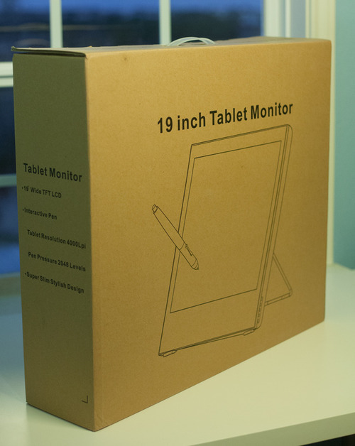
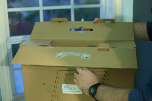
Unboxing, Specs, and the Physical Properties of the Unit

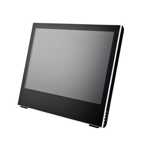
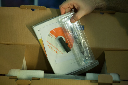
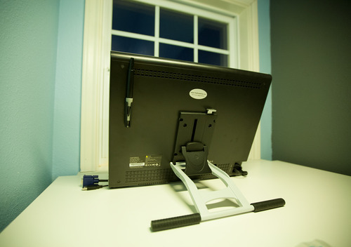
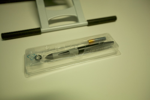
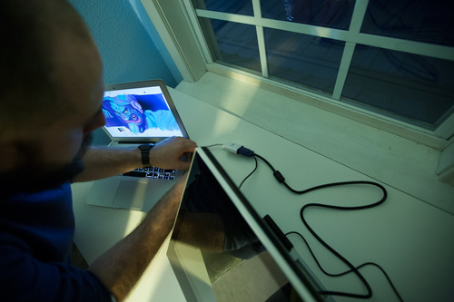
The Yiynova MSP19U is a 19,” 1440×900 tablet monitor with an adjustable, VESA-compatible stand and mounting bracket. It comes with one stylus, one battery, and several additional pen nibs. It has 2048 levels of pressure sensitivity and a 4000lpi digitizer.
The unit is light but not flimsy. Thinner than a Cintiq thanks to its LED backlighting, I find myself occasionally sitting the Yiynova in my lap like a digital art board.
At 19,” 1440×900, and 89.37 PPI, no one will mistake the Yiynova for a retina level display. It’s nearest Wacom neighbor, the 22HD, has a 22,” 1920×1080, and 100.13 PPI, screen. While the Wacom beats the Yiynova in sheer PPI, I always found the color of Cintiqs to be quite muddy thanks in part to an antiglare coating present on the monitors and dim backlighting. I went so far as to remove the glass from my Cintiq to scrape the coating off its back. It helped a little, but was still less than ideal and was not an activity for the faint of heart. Prying, scraping, and modding a $2,499 device to make it useable is a bummer and I went into a lot of detail about the shortcomings of Cintiq tech in my previous review if you want to learn more.
The LED backlighting on the Yiynova makes for a brighter overall display. It’s a little cool out of the box, but was fine once calibrated. If I had to choose between lower PPI or dimmer, muddier colors, I’d pick slightly lower PPI. This particular category is probably a draw.
The glass of the display sits above the LCD by around an 1/8th of an inch and looks to be about the same distance as my previous Cintiq. Until a manufacturer creates a unit with an iPad-like fused LCD and glass display, cursor parallax will be a concern (and is present for both the MSP19U and Cintiqs).
The stand allows for either complete verticality or nearly horizontal viewing angles and is easy to operate. Rotation is not possible, but I find it to be less of a necessity these days. Photoshop, Painter, Manga Studio, and nearly any art app worth it’s salt allow users to rotate the canvas arbitrarily.
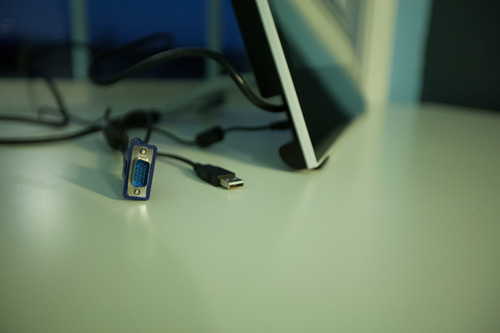
There’s a VGA out port on the back of the monitor that will mirror the activity on your tablet to yet another external display. It’s an odd inclusion, but could be handy for making presentations or when teaching a digital art class. I do both from time to time, so it may be of some use.

Software & Hardware Installation

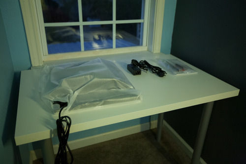
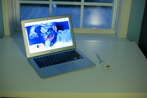
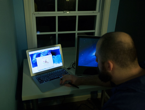
Setup was quick. I tested the unit on maxed 2012, 13” Macbook Air. The Air has a mini display/thunderbolt port, so an adapter was required to pair it with the Yiynova. All in, the MSP19U needs a VGA port, a wall socket, and a USB port to get rolling.
I already had UC Logic drivers installed on my system from my Monoprice tablets, so I only had to plug in the tablet to begin. The bundled driver software is the same version as the downloadable driver on the UC Logic, Panda City, and Yiynova websites, so use whatever is most convenient.
A quick note about drivers. Like with Monoprice tablets, I recommend installing drivers before plugging the tablet in, especially in Windows. Windows will install generic HID (Human Interface Device) drivers otherwise. They’re horrible and you’ll think your tablet is broken. It’s not. You’ll have to uninstall the generic HID driver from device manager, install the proper drivers, and only then plug in your tablet. This mistake accounts for five to ten support emails in my inbox a week.
Some stubborn apps enable tablet specific features (like pressure sensitivity options) only after detecting Wacom drivers present on a system. I install Intuos 3 drivers alongside any alternative tablet hardware to fool these apps into thinking a tablet is present. Painter and Illustrator are the two biggest culprits in my experience in both Win and Mac environments.

Does it work?

I tested the monitor with Photoshop CS6, Painter 12, and Manga Studio 4 and 5 in OSX and Windows. Much like the Monoprice tablets that came before, I found performance even better in OSX than Windows, but fine in both.
There are cursor calibration options in Windows, but no such options in OSX. I didn’t find cursor offset or parallax to be as bad on the Yiynova as on a Cintiq, and never found myself wanting or needing to futz with the cursor offset anyhow.
Cursor lag is similarly less pronounced on the Yiynova than a Cintiq and drawing felt more natural as a result.

A note on Paint Tool SAI. I’ve heard there are some issues running a multiple monitor setup with Paint Tool SAI, specifically, but that’s hard to blame on the Yiynova. SAI has been largely abandonware for some time, and it’s starting to show. I recommend using Clip Paint/Manga Studio 5. It’s a bit like a mashup of SAI, Painter, and Photoshop, and has largely replaced all those other apps in my workflow. My Windows box is a single monitor setup, so I was unable to verify these reports.

The drawing surface is slicker than that of a Cintiq and took a little getting used to. I found that long, deliberate lines could sometimes wobble a bit as my stylus tip slid on the glass, but it was a user limitation, not a failure of the digitizer panel.
Viewing angles on the monitor are worse than a Cintiq, but brightness is better. Viewing angles never veered into unusable territory, but the resolution and viewing angles of the LCD are the single largest area I’d like to see improved in the future.
Bottom line? Is it perfect? No. Are Cintiqs? No.
The Cintiq 22HD costs $1999. It has a slightly laggier feel to drawing, but a higher resolution display and has programmable hotkeys. It’s heavy and cumbersome. At the time of writing, the Yiynova MSP19U costs $569. It has a superior drawing experience in terms of lag and cursor offset to my eye, but a lower quality display and no hotkeys. It’s light and easier to move around a desk or sit in your lap.
Even without the price disparity, I would opt for the MSP19U. Cursor lag was the single biggest complaint I could muster against the Cintiqs and I think the 19U is the winner there. How well it draws trumps how good the image looks for me every time.
But, price matters and we should talk about it. The 19U costs 72% less than the Cintiq 22HD and 77% less than the 24HD. Even if it were marginally worse in all regards – and I find it neither heads and shoulders above or below, simply different – it would still be a steal.
My 19U is now a permanent member of the household. I don’t plan on, or feel the need to, replace it with a Cintiq.
Wacom has genuine competition on both the tablet and tablet monitor fronts. Spread the word. Make them feel some heat. There’s no reason this technology should be so expensive. The underlying hardware has been largely stagnant for a decade with no real innovation.
At $569, and with performance that often meets or exceeds Wacom’s hardware, the MSP19U is more than a viable alternative. It’s the disruptive agent of change the industry needs.
« Newer Posts

Powered by WordPress

error: Content is protected !!